 |
HapticLib
0.7
Haptic Feedback Library for embedded systems
|
 |
HapticLib
0.7
Haptic Feedback Library for embedded systems
|
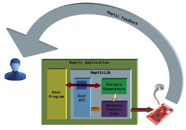
HapticLib structure is composed of different parts working together to expose a simple API to the library user.
The main blocks are:
Concept of Operations:
The user program code uses documented API from the User API module (basically #include "hapticLib.h" lists the API function offered). The User API module then forward the application requests to the other modules. For the initialization phase, and for any hardware interaction, the Platform Specific module is always called ultimately. For anything related to the Haptic patterns generation, the Pattern Generator module is the one doing the hard work. Here the User API module act just as proxy for the application code to call the right pattern generator function, allowing for transparent extension of the Library without breaking existing code.

The User API module is the direct interface to the HapticLib user's application code. The developer should start from this module to learn how to use HapticLib.
Here is a simple use case.
The program starts initializing the system.
       uint32_t frequency    = 12000000;  // PWM frequency set to 12MHz.
       uint8_t  sampleDelay  = 10;            // PWM inter-samples delay 10ms.
       uint8_t  numHaptors   = 3;         // Number of haptors used

       haptor_desc *myHaptors;                    // haptor descriptors array.

       myHaptors = hl_configure(frequency, sampleDelay, numHaptors);
Then the program must initialize the patterns used in the application:
      pattern_desc *myPattern;

      myPattern = hl_initPattern(Test, NULL);

      hl_addHaptor(&myHaptors[1],myPattern);
Now the pattern can be started:
hl_startPattern(myPattern);
And stopped (if the pattern has not finished yet):
              Delay(2000);

      hl_stopPattern(myPattern);
That's it!
From an Interface point of view, there is nothing more to do for the system to work. It is up to the developer now to implement the right behavior of the application.
HapticLib offers a lot more than this simple and plain example. You can simultaneously start different patterns on different haptors. The patterns will run concurrently together.
Even more, multi-haptors patterns can be setup to drive different haptors under the same haptic logic (just call hl_addHaptor() multiple times on the same pattern).
HapticLib uses a pattern scheduler to implement this features. If you want to know more, pleas refer to the Developer Guide page.
Please, make sure to also read all the other documentation; in particular check:
The interaction with the hardware is done in this module. Actually this module is composed of a pair of .c/.h files for each hardware platform supported by the library.
During the initial configuration phase, the high-level hl_configure() function calls the right implementation of the low level routines based on the platform specific symbols defined. (for example STM32VLDISCOVERY).
If a platform provide a peripheral driver library, this module can make use of it greatly simplifying the code. For example the STM32VLDISCOVERY board is based on a STM32F10x MCU that is supported by STM's StdPeriph Library.
Every platform have its characteristics, so it is important to read about HapticLib implementation for that platform that impact on the high level behavior of the application.
Here is the list of supported platforms:
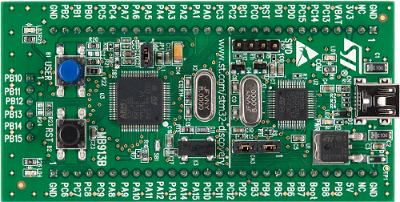
This board from STM uses a STM32F100RB ARM based MCU. The library development started on this board, so it is well supported.

Here the interesting specifications of the MCU from a HapticLib perspective:
For detailed informations refer to STM documentation.
The STM32VL-DISCOVERY Developer Board features:
Also from STM, the StdPeriph is used to simplify hardware addressing.
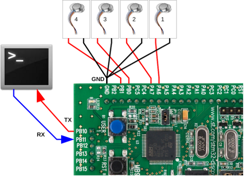
The STM32VL-DISCOVERY Dev Board, can generate more than 20 PWM control signals directly mappable to GPIO via Alternate Functions. However the HapticLib's STM32VLDISCOVERY Platform Specific module only supports 4 haptic devices to be driven by the application. Future release may add support for additional haptic devices for this platform.
Here is the haptic device hardware layout supported:

The Serial link available on the PB I/O port, is enabled only when the HL_DEBUG symbol is defined at compile time.
To understand how the Pattern Generators module works, let's start describing the sequence of events happening when the user starts a pattern.
When the user application code calls hl_startPattern() (after the initialization step), the User API module forward the call to the initiator of the pattern passed as parameter.
Once called, the pattern initiator validate the user parameters. If the parameters are valid, the initiator will setup the its initial status, and the pattern instance becomes running.
When the pattern instance becomes running, the pattern scheduler will start calling its continuator every time the inter sample delay elapses.
When the pattern ends (if it ever ends) the continuator will remove the pattern instance from the scheduler freeing the resources used (the haptors).
Alternatively, if the pattern is still running and the user needs it to stop (or needs the haptors for other patterns) the hl_stopPattern() API function can be called to force the pattern de-scheduling and resources freeing.
Now that the running flow of events has been described, we can show the Pattern Generator typical structure.
A Pattern Generator is a sort of module plugged in HapticLib. It is composed of two functions:
and two data structure type definitions:
The initiator for a pattern instance gets called only once; when the user application code calls hl_startPattern().
Its job is to setup the initial status of the pattern and schedule the instance for running to the patternScheduler().
The continuator for a pattern instance is called by the patternScheduler() every inter-sample delay (after the initiator scheduled it) as long as the pattern instance is running. The haptic feedback logic of the pattern decides when to stop the instance. During its last run, the continuator will de-schedule the pattern instance from the scheduler, and free all the resources used (the haptors).
A Pattern Generator also defines two data structures to hold the informations needed at runtime.
The user parameters is a type definition based on a structure holding all the data the user can fine-tune when creating a new pattern instance.
It is important to read the documentation of the pattern to be used, to understand the meaning and the use the pattern will make of every single parameter passed by th user.
To better understand, here is an example of user parameters for an existing pattern, the impact pattern generator.
The user parameters accepted to personalize a pattern instance are:
One instance could send the haptic feedback of a fast impact on a wood surface, then another instance could send the feedback of a slow impact on a rubber surface.
Refer to the impact pattern generator documentation for detailed informations.
The status parameters structure is an internal container of the pattern instance status and progress. It is not exposed to the user, nevertheless it is important to understand that internally the pattern initiator will setup the starting status (probably depending on the provided user parameters) and that the continuator will update the status parameters at every patternSchedule() call based on the logic and the progress of the pattern.
The following examples will describe some uses of the library showing the way to use the User API and the different kind of pattern existent.
Under the Demos/ HapticLib sub-directory are present different demo applications.
HapticWorld is the simplest demo possible, showing how to use HapticLib API.
This demo activate a single haptor test pattern and then exits.
The main.c code is listed below, interleaved with the descriptions.
#include "hapticLib.h"
This include will enable HapticLib in the application.
   enum demoHaptors {
        Head          = 0,
        Lhand         = 1,
        Rhand         = 2,
        Back          = 3,

        NumDemoHaptor = 4
   };
This enumeration will make the code cleaner when referring to the haptor descriptors array.
   int main(void)
   {

        // Pointer to the array containing the setup haptors.
        haptor_desc *myHaptors;

        // Initialize the Haptic System and get the haptors array.
        myHaptors = hl_configure(24000000, 10, NumDemoHaptor);
Here the reference to the set of haptors used by the application is declared and initialized. NumDemoHaptor can be less than the total available system haptors. From now on every haptor can be referenced in this way:
myHaptor[Head] for the first haptor myHaptor[Lhand] for the second, etc.
        // We are ready to send patterns.

        pattern_desc *myPattern;

        // Use a Test Pattern
        myPattern = hl_initPattern(Test, NULL);
myPattern is the descriptor of the test pattern we want to use. In this case the second argument of hl_initPattern() is NULL because the Test Pattern does not accept any user parameter.
        // We need to tell the Test pattern which haptor to use
        hl_addHaptor( &myHaptors[Head], myPattern);
The pattern is now setup, but it doesn't know yet on which haptor to work. hl_addHaptor() link the given haptor to the given pattern. In this case myHaptor[Head] is used.
        // Start Shaking
        hl_startPattern(myPattern);
The hl_startPattern() call activates the feedback execution.
In this particular Pattern and with the settings given to hl_configure()the pattern activation will last for some time (about 2 seconds).
        // Let it shake for a while...
        Delay(1000);

        // ...or force its stop if we need the haptor for something else.
        hl_stopPattern(myPattern);
To show the forced stopping of the pattern, hl_stopPattern() is called after 1 second wait (in the middle of pattern execution).
   #ifdef HL_DEBUG
                send_string("\r\nHapticWorld: Going to sleep...goodbye!\r\n\0");
   #endif

        // go to sleep
        while(1) { __WFE(); }
   }
In the end the program goes to sleep.
HapticCalbirator is a demo application that let the user calibrate the minimum PWM duty cycle for an haptor that delivers a vibration strong enough to be felt.
The HapticCalibrator demo will show how a continuous pattern works, how is possible to modify a user parameter during a pattern execution.
The main.c code is listed below, interleaved with the descriptions.
   #include "stm32f10x.h"
   #include "hapticLib.h"
In addition to HapticLib include, this application will use some hardware peripheral directly, that's the reason for the STM include.
   int main(void)
   {

        haptor_desc *myHaptor;
        user_param   myParams;

        myHaptor = hl_configure(24000000,10,1);
Here the reference to the haptor used and the pattern's user parameters are defined.
Then the haptor reference is initialized with hl_configure().
        // User Button Event Configuration
        GPIO_EXTILineConfig(GPIO_PortSourceGPIOA, GPIO_PinSource0);
        GPIO_EventOutputConfig(GPIO_PortSourceGPIOA, GPIO_PinSource0);

        EXTI_InitTypeDef InitStruct;
        InitStruct.EXTI_Line    = EXTI_Line0;
        InitStruct.EXTI_Mode    = EXTI_Mode_Interrupt;
        InitStruct.EXTI_Trigger = EXTI_Trigger_Rising;
        InitStruct.EXTI_LineCmd = ENABLE;

        EXTI_Init(&InitStruct);

   #ifdef HL_DEBUG
        send_string("\r\n\r\n\0");
        send_string("\t\tWelcome to HapticCalibrator!!\r\n\r\n\0");
        send_string("Now we will calibrate the System's Haptors...\r\n\0");
        send_string("As soon as you CLEARLY feel the vibration, hit the User Button!!!\0");
        send_string(" ( Be quick! ;) )\r\n\r\n\r\n\0");
   #endif

        Delay(1500);

   #ifdef HL_DEBUG
        send_string("Wear the Haptor and when you feel ready, press the User Button.\r\n\0");
   #endif

        while ( EXTI_GetFlagStatus(EXTI_Line0) != SET ) { __WFI(); } ;

        EXTI_ClearFlag(EXTI_Line0);
This piece of code is specific to this application. The EXTernal Interrupt is configured with the User Button (PA0), and then the program waits (sleeping) for the user to press the User Button and let the calibration begin.
        myParams.constant.constant = 0x0000;
        hl_startPattern( hl_addHaptor(myHaptor, hl_initPattern(Constant, &myParams) ) );
The pattern used in this application is the Constant Pattern. It takes a user parameter constant that represent the duty cycle of this haptor's PWM.
The starting of the pattern here is condensed using call nesting of functions.
To call hl_startPattern(), hl_addHaptor() must be called first, and likewise hl_initPattern() is required by hl_addHaptor().
So the actual sequence is:
The initial duty cycle is 0x0000.
        while ( myParams.constant.constant < 0xff00 )
        {
   #ifdef HL_DEBUG
                send_string("Duty Cycle: \0");
                send_int(myParams.constant.constant);
                send_string("\r\n\0");
   #endif
                myParams.constant.constant += 10;

                Delay(1);

                if( EXTI_GetFlagStatus(EXTI_Line0) == SET )
                {
                        EXTI_ClearFlag(EXTI_Line0);
   #ifdef HL_DEBUG
                        send_string("GOOD! We found the minimum dutyCycle!\r\n\0");
   #endif
                        GPIO_WriteBit(GPIOC, GPIO_Pin_8, Bit_SET);
                        break;
                }
        }
Now a cycle is started to increase the duty cycle at every iteration. And when the user presses the User Button, the cycle is interrupted.
        if( myParams.constant.constant >= 0xff00 )
        {
   #ifdef HL_DEBUG
                send_string("BAD!! We reached almost the 100\% DutyCycle and you didn't press.\r\n\0");
                send_string("Make sure your Haptor isn't broken!\r\n\0");
   #endif
        }
        else
        {
   #ifdef HL_DEBUG
                send_string("Now setting the minimum activating DutyCycle to: \0");
                send_int(myParams.constant.constant);
                send_string("\r\n\0");
   #endif

                myHaptor->min_duty = myParams.constant.constant;
        }
Here a check is made to verify the user really pressed the button and the duty didn't reach the top instead.
If the user pressed the button, the haptor's minimum duty cycle is updated with the value set by the user.
hl_stopPattern(myHaptor->activePattern);
The Constant Pattern is a non stop pattern, this means the user application must call hl_stopPattern() to end the pattern and free the haptor.
   #ifdef HL_DEBUG
        send_string("\r\nGoodbye....going to sleep...\r\n\0");
   #endif

        while(1) { __WFE(); }
   }
In the end the program goes to sleep.
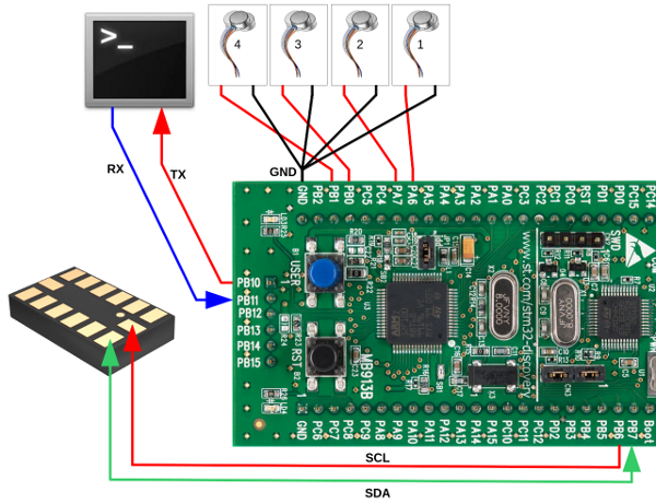
HapticLevel is a very simple, real world example demo showing how easy is to implement haptic feedback embedded applications. HapticLevel acts as an electronic Level to measure a surface's tilt. The device uses 4 haptors (one for each direction) and one 3-axis accelerometer (STM's LIS302DL). The haptors are connected to the board's GPIO, the sensor is connected to the I2C1 peripheral, and the serial console (enabled only in debug versions) is connected to USART3 as usual.
Here is the complete system layout:

The haptors are placed in pairs along orthogonal axes. When the device is placed on a surface, it will "display" the tilt activating one haptor for each direction.
Now that the device has been described, let's look at HapticLevel's code.
HapticLib knows nothing about the LIS302DL sensor and all the relevant code is jut part of the demo.
To unclutter main.{c,h} source code files, another module has been used to place all sensor specific code.
LIS302DL support SPI and I2C interface. I2C has been used. Routines to manage communications with the sensor are based on existing code by Michele Magno and Bojan Milosevic (MicreLab University of Bologna) located on lis302dl.c, lis302dl.h HAL_LIS3LV02DL.h source code files.
In main.c the fist thing the program does is to init the I2C1 peripheral and then init the sensor as well:
    // I2C1 peripheral Initialization
    LIS3LV02DL_I2C_Init();

    // LIS302DL Sensor Initialization
    LIS3LV02DL_Acc_Init();
The next thing main() does is to initialize HapticLib library, configuring the four haptors, setting up the Constant pattern, and attaching the haptors to the pattern.
    // Haptors Initialization
    // Initialize the Haptic System (setting the PWM global period in Hz)
    haptors = hl_configure(24000000,10, NumLevelHaptors);
    // Start each haptor
    for( i=0 ; i<NumLevelHaptors ; i++)
    {
      levelParams[i].constant.constant = 0;
        if(  hl_startPattern(
               hl_addHaptor(  &haptors[i],
                      hl_initPattern(Constant,&levelParams[i]) ) )  )
        {
   #ifdef HL_DEBUG
        send_string("HapticLevel: Problem Starting Haptor \0");
        send_int(i);
        send_string(".\r\n\0");
   #endif
        }
    }
The starting intensity is set to 0 for each pattern, so they will not vibrate. Now the actual application logic kicks in; the program enters an endless loop where the values of x,y,z acceleration are read from the sensor. The z-axis is used to sense the actual orientation of the device (upside or downside). Then the x and y axis are used to decide which haptor of each pair will vibrate with a new constant value proportional to the entity of directional tilt. The other haptor of the pair is simply kept to a constant value of 0 to prevent vibration.
    while(1) {

    // Get X-axis value
    LIS3LV02DL_Acc_Read_RawData(&tmp,LIS_A_OUT_X_L_ADDR);
    x = (int8_t) (tmp >> 8);

    // Get Y-axis value
    LIS3LV02DL_Acc_Read_RawData(&tmp,LIS_A_OUT_Y_L_ADDR);
    y = (int8_t) (tmp >> 8);

    // Get Z-axis value
    LIS3LV02DL_Acc_Read_RawData(&tmp,LIS_A_OUT_Z_L_ADDR);
    z = (int8_t) (tmp >> 8);

    #ifdef HL_DEBUG
        send_string("HapticLevel: X-Value \0");
        send_int(x);
        send_string(".\r\n\0");
    #endif

    // positive orientation
    if( z >= 0 ) {
            if( x >= 0 ) {
                levelParams[Up].constant.constant     = 4096*x;
                levelParams[Down].constant.constant   = 0;
            }
            else {
                levelParams[Down].constant.constant   = -4096*x;
                levelParams[Up].constant.constant     = 0;
            }
            if( y >= 0 ) {
                levelParams[Left].constant.constant   = 4096*y;
                levelParams[Right].constant.constant  = 0;
            }
            else {
                levelParams[Right].constant.constant  = -4096*y;
                levelParams[Left].constant.constant   = 0;
            }
    }
    else { // negative orientation
            if( x <= 0 ) {
                levelParams[Up].constant.constant     = -4096*x;
                levelParams[Down].constant.constant   = 0;
            }
            else {
                levelParams[Down].constant.constant   = 4096*x;
                levelParams[Up].constant.constant     = 0;
            }
            if( y <= 0 ) {
                levelParams[Left].constant.constant   = -4096*y;
                levelParams[Right].constant.constant  = 0;
            }
            else {
                levelParams[Right].constant.constant  = 4096*y;
                levelParams[Left].constant.constant   = 0;
            }
        }

        // Sleep
        Delay(100);

    }

    while(1) { __WFE(); }
The main() code enters an endless loop where it polls for new values of the 3 vectors (x,y,z) from the sensor.
The single direction value is retrieved calling LIS3LV02DL_Acc_Read_RawData() with the first argument being a pointer to int16_t value and the second argument the direction to be retrieved.
The values are then casted to 8 bit signed values.
The first check is on z-axis value to understand if the device is up-face or down-face.
Then the x and y-axis are checked to know the device tilt on each direction.
If the axis value is positive, a scaled value of the sensed amplitude is set as duty-cycle for one haptor. (and a zero duty is set for the opposite one). If the axis value is negative, the same happen but with inverted haptors.
Note the negative scaling coefficient for negative direction. This is needed in order to have coherent proportional intensity variation on tilt.
The last line of code should never be reached.
HapticLib offers some debugging features to ease application development and bug hunting.
The debugging features are made of two utility functions:
Implementing those functions, the user won't need any additional code library for basic I/O across a serial link.
All the debugging code inside the library gets conditionally compiled if the preprocessor symbol HL_DEBUG is defined by the user, allowing the complete removal of any debugging code on the release version of the application.
The user application code must adhere to this technique, enclosing any debug related code inside preprocessor rules:
    #ifdef HL_DEBUG

        // Debugging code

    #endif
The HL_DEBUG preprocessor symbol must be defined in order to enable the debugging features. Th best place to do this is adding the definition on the compiler invocation command. For example:
gcc ... -DHL_DEBUG ...
The Makefile available from the template Demo application defines a variable to easily manage the compilation of DEBUG and/or RELEASE target version of the application.
This utility function allow the transmission of a string representation of any unsigned long integer number ( uint32_t ).
The number is always printed in hexadecimal format ( 0x... ) and additionally, if the value is less than 100000, the decimal representation is print too.
For example:
send_int(256);
will output the following string:
0x100 (256)
meanwhile:
send_int(456789);
will output:
0x6f855
This utility function allow the transmission of a string across the serial link.
The string will be trimmed to 255 characters.
If the string passed has a null terminator ( '\0' ), only the characters preceding it will be printed.
For example:
send_string("Hello World!\n\rGoodbye World!\0Not this");will output:
       Hello World!
Goodbye World!Both send_int() and send_string() functions rely on the function send_char() to actually output every single character.
send_char() is a platform specific function.
Each platform must implement the send_char() function to enable the debugging features.
For example, the STM32VLDICOVERY platform module uses the USART3 as serial link for debugging messages.